Past and Future at Total's Elgin/Franklin Project
Posted by JoulesBurn on April 25, 2012 - 11:00am
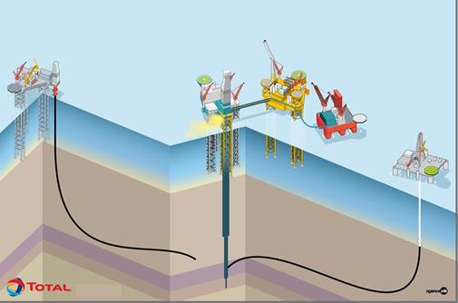
Four weeks after the Elgin G4 well sprung a leak above the production platform in the North Sea, Total has spudded the first of two relief wells as backup in case the attempt to kill the well from above doesn't work. It will take 6 months to drill the wells, however, and an estimated 200,000 cubic meters of gas per day was initially being released, and reportedly enough so far has leaked to heat all of Aberdeen for a decade (a suspect claim, perhaps).
In this post, I will provide some additional background on the history of this project and what Total E&P UK's plans were prior to the leak and subsequent shutdown of all production.
|
| Figure 1: Relief well plan for Elgin G4. Source: Total |
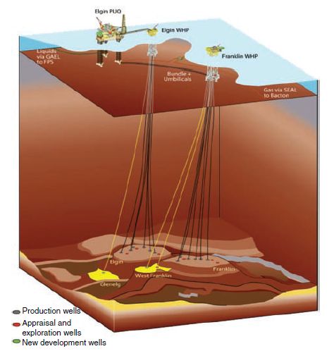
In my previous report on Elgin, I gave a brief description of the facilities. There are currently two wellhead platforms, one (with the leak) tethered to the Elgin PUQ platform with a bridge, and the other connected to the PUQ [production-utilities-quarters] platform with underwater pipelines (Fig. 2).
|
| Figure 2: Elgin/Franklin Project. source: Journal of Petroleum Technology, 2011 |
Some noteworthy items in this graphic:
- The Franklin wellhead platform is 5.4 km from the Elgin PUQ and wellhead platform
- According to this publication, in 2011, seven production wells are tethered to the Elgin platform: six in the Elgin field and one in the Glenelg field. Note that there are a total of 12 well slots on the Elgin platform.
The original plan is described in Elgin/Franklin: What Could Have Been Done Differently? (third article in pdf, hence referred to as WCHBDD).
The development was based on 12 wells (seven on Elgin, five on Franklin) and included the recovery of two predrilled appraisal wells. Provision was included for a second Elgin wellhead platform, also bridge connectable to the process utilities and quarters (PUQ) platform, to be installed later if warranted.
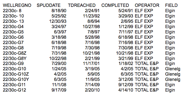
Information on the wells drilled for this project are available from the UK government. Shown in Table 1 are those which were drilled near where the Elgin platform is now located, and which could potentially occupy slots.
|
| Table 1: Wells potentially connected to Elgin platform. |
The first three wells were exploration wells, and were subsequently named G1, G2, and G3. It was hoped that these could be used as producers, but this did not work out in the end. In the main development phase, wells G4-G8 were drilled prior to any production. However, the first attempt with well G8 experienced problems, and must have been sidetracked (G8Z) and then again (G8Y). Well G9 was completed sometime after production started in 2001, and thus only 3 empty slots were available at the beginning of 2002. As WCHBDD reported:
Failure in recovering Elgin appraisal wells meant that a total of only six slots remained available for future drilling (three on Elgin and three on Franklin), instead of nine as planned.
The nearby Glenelg field was discovered in 1999, and a production well tethered to the Elgin platform was drilled in 2005-2006 (again after 3 tries). G11 and G12 are recent infill wells into the Elgin field.
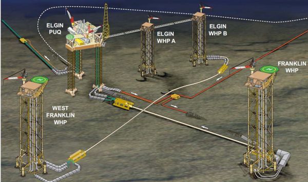
This would imply that all 12 slots were then occupied. Time for the 2nd Elgin platform. A recent Total presentation revealed that development of additional facilities was under way, including a second Elgin platform and one for the West Elgin field as well. Indeed, the installation of the platform jacket (the supporting tower) was supposed to take place in September of this year.
|
| Figure 3: Elgin/Franklin current and future infrastructure |
But let's go back a few years. Things were off to a good start, according to WCHBDD:
Overall, the Elgin/Franklin asset was off to a good start when first production began in 2001, with expected production already higher than planned at project sanction.
Unfortunately, not all of the original producers lived into old age. A presentation (6 MB pdf) by JL Bergerot of Total in February of this year had this plot (Fig. 4):

|
| Figure 4: Elgin/Franklin wells that ended not so well. (click image for larger version) |
The slide had the following text:
Why is HPHT [high pressure high temperature] infill drilling challenging ?
Drilling infill wells in Highly Depleted Reservoir is a strong challenge.
- unability to achieve reliable wells on some fields (loss of 3 wells due to liner full collapse, 1st infill stopped due to a technical difficulty)
- serious troubles on a field depleted by 140 bars only.
Very rapid and important depletion is usual on HP/HT fields
The reservoir started out highly overpressured, but then drops rapidly with production. Well G5 and the G10(Y?) wells apparently died in late 2006 due to liner collapse.
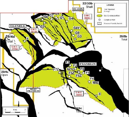
A Total presentation at the 23rd World Gas Conference in June 2006 had this map (Fig. 5):
|
| Figure 5: Elgin/Franklin wells showing status |
Note that the Elgin wellhead platform is directly over the G1 well (and the Franklin platform over the F2 well). This map is from about 2006, and shows more detail on the delineation of the fields. A seeming differentiation is made between shut in wells (G1 and G2) and a fully killed well (G3).
And I found other tidbits: On 17 August 2011, the North Sea Reporter reported "On Elgin, the Rowan Viking continues with slot recovery work in well 22/30c-G8y". And one person's LinkedIn page has this:
Working back on Elgin Franklin as wireline supervisor on the G8 well kill and slot recovery programme following the unexpected separation of the production tubing. This was an extensive programme, which involved a lot of unique one off, tooling to permit access to the production tubing and prepare the well for slot recovery at a later time via a drilling rig. This took almost 3 months altogether and was delivered successfully and safely in collaboration with a number of other contractors to the client. The installed assemblies were later recovered successfully when the Drilling Rig Rowan Viking was brought in to recover the slot.
So well G8 is dead as well, and the slot was being freed up for reuse within the last year. One more from LinkedIn (since July 2011):
Lead the planning of challenging infill HPHT development wells: Elgin Infill C (high depletion, sour environment, slot recovery with live annuli, coil tubing killing, first Elgin well abandonment), West Franklin C/D/E (T° ± 223°C, new material and connections qualifications, compaction mitigations, pipe in pipe architecture solution, pre-drilling with deep tie-back and tie-back at MLS...)
Possibly the same G8Y well, but strange that it would be referred to as infill. Live annuli?
The Dreaded Hod Formation
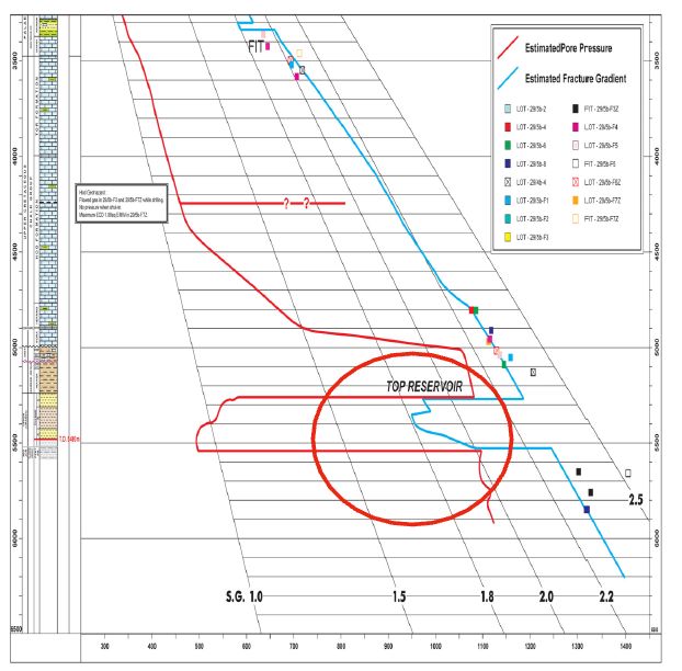
Two problems seem to have been evident for a long time. The first is the rapid pressure depletion, which has resulted in well deformation and death, plus makes it difficult to drill infill wells as the "mud window" between the formation pore pressure and the fracture gradient disappears. Although the reservoir is depressurized, the cap rock above is not. So a certain mud weight is necessary to contain the well during drilling above the reservoir becomes excessive when drilling through the reservoir, possibly leading to mud circulation loss and formation damage. From another Bergerot presentation:
|
| Figure 6: Mud window loss and Hod formation. |
Fig. 6 shows the situation with the reservoir depressurized by production. But note that spike at about 4250 meters. This thin overpressurized Hod zone is what is believed to be causing grief on well G4, and has been a problem from early on. The text box next to it reads:
Hod Geohazard
Flowed gas in 29/5b-F3 and 29/5b-F7Z [Franklin wells] while drilling
No pressure when shut in
Maximum ECD 1.88sq EMW in 29/5b-F7Z
From Predicting Effects of the Hod Geohazard:
Because the gas-bearing Hod limestone is overpressured and tight, gas is able to percolate into the wellbore during drilling and also during completion operations when the casing is depressurized. Realizing that cemented casing was unlikely to hold gas back during well production lifecycles, casing-annulus pressure-management systems were installed on the facilities. In addition to increasing awareness of the Hod gas influx during drilling, fit-for-purpose mitigation plans were conceived.
There are some Hod-related references in an extended abstract from an HPHT meeting in 2009:
22/30c-G11, was drilled in 2009 into the Elgin Field with a depletion
in the order of 700bars. This well planned for the events that occurred in 29/5b-F8Z,
but also contingency planning for high gas levels in the cap rock as this had been
encountered in a number of the development wells. Whilst drilling, gas events were
encountered much higher and more continuously, from the top of the Hod Formation
and at further intervals throughout this Formation. The origin of these unexpected gas
events is still under investigation.
...
This well was eventually successfully completed and brought into production
in October 2009.
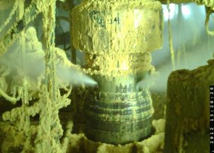
Finally, there are two questions I have involving this image (Fig. 7) of the leaking wellhead:
|
| Figure 7: Leaking Elgin wellhead |
- What is that yellow stuff?
- How did/does it form?(recalling that the Hod formation gas does not have significant H2S)
It has been reported that the rate of gas leaking from the well has decreased by two thirds (or perhaps that the estimate is 2/3 less), but the actual headline says more about the current state of energy journalism than anything else.
Contact
- Content: editors at theoildrum dot com
- Tech support: support at theoildrum dot com
License

This work is licensed under a Creative Commons Attribution-Share Alike 3.0 United States License.
These leaks will become a permanent news story in the years ahead it seems. What if a super giant gas field is discovered underwater- and has a blowout? What will the effect be on global warming of thousands of little underwater leaks and of many fracking leaks?
Extreme exploration seems, almost by definition, to be reckless exploration. Going into a less controllable area to drill is a reckless decision- no matter how many precautions are taken. Just like speeding 100 mph is a reckless decision, no matter how carefully you drive.
Could increasing extreme exploration constitute a Peak Oil feedback loop that amplifies global warming?
Analogous to an earlier era of drilling with cable tools.
"These leaks will become a permanent news story in the years ahead"
Only if there's explosions and fire and death and TV pictures... :(
http://www.youtube.com/watch?v=mSujCHfvTb0
good ole clark and dawe.
Considering the shallow depth my money is on biologic material being the stuff and either false color or overexposure from the close in lights making it look more yellow than green. OTOH depending on the way way H2S enters solution from high pressure and the 4+ week duration of the leak, even if there is very little H2S comming from the well it could still build up over time.
The wellhead is high above the water line. Someone else posted on another thread that it is a combination of waxy condensate and hydrates.
I recall a news report that stated that part of the plan was to remove waxy deposits from around the well head. Sorry I can't be more specific.
NAOM
Elgin Stakeholder briefing VA 13 April (pdf)
http://www.asmconsortium.net/Documents/Elgin%20Stakeholder%20briefing%20...
"(A team of specialists) has since returned to perform a number of preparatory tasks ahead of the proposed intervention. This included a clean-up of the platform areas surrounding the G4 well where soft waxy deposits formed from leaked condensate had accumulated (see photo)."
The photo is of the gas leak and light green "stuff".
http://www.offshore.no/international/article/Leaking_Elgin_condensate_wi...
"“The condensate is a very paraffinic fluid,” Total says. “As soon as it is released from the well head, a soft waxy deposit is formed on the cooler surfaces of the wellhead platform.”"
This also makes sense in that the lighter condensate would wash the greenish wax away from below the exit points. The picture shows a clean zone below where the gas is escaping.
Image: Bottles of condensate with wax at the bottom
http://www.pegresol.com/images/waxmix.jpg
Image: wax
http://www.pegresol.com/images/before_after.jpg
I was working with running engines on HDPE milk jugs. HDPE is essentially solid "gasoline"... solid alkane. The light green is the same color as the wax that would condense from the gas made by thermally decomposing the plastic.
http://www.youtube.com/watch?v=BbKSSr9ypts
No beard was lost during these efforts.
Graphic: The ranges of how many carbon atoms (carbon number) in Natural Gas, NG Condensate, and Light Crude through Oil Shale... -Really Nice-
http://tigger.uic.edu/~mansoori/Polydispersivity.JPG
Really nice paper on petroleum fluids - -Really Nice-
http://tigger.uic.edu/labs/trl/1.OnlineMaterials/09.IJOGCT.020203.MANSOO...
From:
http://tigger.uic.edu/~mansoori/HOD_html
___________________________________
O.K.
So... what are the holes? Someone said they were where the hanger bolts were... hanger clamp was? ... that the wellhead has come apart... subsidence? Pressure?
Thanks for filling in the detail.
NAOM
The “decade” of heating quoted refers to deferred (not really lost) production of 81.2 billion scf because the facilities have been shut down, not the actual leaked gas (which may really be lost or may be coming from non-producable areas of the reservoir if I understand correctly). The 200,000 cubic meters figure was the initial estimate of daily gas leak (7 to 8 million scf), which has now fallen to 75,000. So total leaked gas would be around 150 million scf or 0.2% of potential production. over the period 81 billion sounds about right for a decade of demand for a town of 100 to 200,000 households like Aberdeen.
The yellow deposit might be calcite (calcium carbonate) which could come out as the pressure is let down on any produced water which is produced with the gas. Other possibilities are siderite (ferrous carbonate) from corrosion of iron by carbon dioxide in the gas – but I think this less likely as the piping material would likely be corrosion resistant alloy, or pyrites (iron sulphide) but there is supposed to be low sulphur content. However even when gas is said to be sweet it might mean just around 10ppm H2S, i.e. not enough to cause any problems in normal operation, but even this amount could produce some effect over time. Even at high H2S content elemental suphur would not deposit out. There are other scale or corrosion product minerals that could appear yellow, especially if containing some impurities, and without knowing the chemistry of the well and the type of materials in the piping it is difficult to speculate with much certainty.
If that is the case, then there is hope the leaks will scale themselves shut.
That would be black and it could get hot enough when exposed to air to initiate combustion.
Score: 1 good and 1 bad, very bad but not likely.
So is the upshot of this that the well will flow until a relief well can be completed?
Is there any reason otherwise to start a relief well if there is good confidence that the well can be plugged from the platform?
By drilling the relief wells, they may be trying to scare the well into letting itself be killed.
et - I'm not sure how confident they really are. The standard oil patch position: there is your plan and then there's what actually happens. About two weeks ago they issued a statement that the surface kill plan would be attempted in a month. IOW just two weeks from when the relief well spudded. It's one thing to have the rig on location standing by...another to go thru the expense of spudding in. If I had "good confidence" in the top kill effort I might have waited the two weeks.
But can't ignore the possibility the top kill effort could ignite the well and turn a bad situation into a very terrible situation. That risk might be low but it isn't zero. If this were to happen and they hadn't started drilling the second guessers would have had a field day.
Sounds like the oil patch is just another battlefield, defined as a place where, according to Napoleon, no plan survives collision with the enemy.
Separately, the photo of the escaping gas makes it appear that the leak is at a point where the pipe section coming up from the well tapers down to a constant diameter.
Is there a seal at that point that is leaking or is something ruptured? Can anyone elucidate which of the nested set of pipes shown in the TOTAL wellhead diagram we are looking at?
Refer to this diagram:
(click image for larger) from here:
http://www.elgin.total.com/elgin/content/documents/elgin_gas_leak_press_...
Back in the first post on this Toolpush said
From what Total's diagram showed I looked like all strings of casing bar the 30" has failed/leaked/burst, that your pick. Now this sounds very extreme, and I would like to see more information from Total before getting carried away with that as a conclusion. Facts seem very thin on the ground one week after the event.
I am surprised that none of the North Sea drilling hands have not offered any of their wisdom, or inside information on the matter!
If you look at the little red arrows that are supposed to show the path of the leak you will also notice that in the lower section of the drawing gas has made it to the 'C' annulus and then in the upper section is has magically appeared in the 'D' annulus somewhere between the seabed and the point top of the piping. I took Toolpush's comment to imply this drawing (which I posted originally) is of questionable value.
Given the comments made about well deformation/collapse in the discussion of Elgin as an example of producing a HTHP field, maybe TOTAL has more information on the specifics of this failure than they have publicly disclosed.
Still, if the entire set of pipes is compromised, how is a top down kill even possible? Is there hope that the mud would plug whatever holes in the drill strings that are leaking even though the gas might just be expected to froth it away?
Yair . . . Guday folks. I've been off line with computer issues but a week or so back I asked Rockman or some other oil patch folks what those yellow deposits were . . . I thought it may have been sulphur, it sure is the right colour.
I also asked if anyone could give us a "talk through" of what we are looking at in the photo. One of the problems is lack of scale, what would be the diameter of that taper and just what is it exactly?
We can see gas exiting two holes and, from their location, it would not be unreasonable to assume there there may be two other holes venting out of view on the other side.
Nothing appears to be bent or broken, what may have happened to allow this catastrophe to happen?
These queries may have been addressed somewhere but I havn't had time to check the posts. Can any one help or bring me up to speed?
Cheers.
SP - Various ideas as to the comp of the yellow stuff have been offered. Usually some sort of mineral percipitate. I hadn't contributed to those thoughts until now. Not sure what the color is due to but some of the crystals could be ice. When NG under pressure is subjected to a rapid drop in pressure the water vapor in it can freeze. Often when we produce a well through the surface producion equipemnt we actually use a "line heater" to keep the NG from freezing up the plumbing. often burn part of the NG production to fuel the heater. So even if the bottom hole temp is several hundred degrees you can still freeze a flow line solid due to the pressure drop.
As far as scale goes I can only offer a generic possibility. An offshore well head like this could be 10' - 20' tall and 60" at the max base. Just a WAG but you're probably looking at 3' diameter section in that pic.
I think kalimandu' answered that above:
Yes, it's paraffin wax which is condensing out of the natural gas as it blows out of the wellhead and hits the cooler North Sea air. That's why they call it "condensate". The majority of the condensate is more like gasoline and just drips into the ocean and floats away.
The wax is yellow because... it's yellow paraffin wax, I guess. I don't think anybody is going to bother to do a chemical analysis to determine what's in it.
I'm late to the Peak Oil bandwagon - but I'm catching up quickly.
http://i44.tinypic.com/2v9yx37.png
Yes maybe, but well now, Aberdeen can share its lost heat right away with the rest of the world.
Funny, but it'd be so much funnier if it wasn't so true :-(.
It would be more funny if there was some actual truth in it.
It's in the range that in the Canadian oil industry we would get a letter from the regulatory authorities saying that they thought it would be nice if we stopped flaring the gas from our oil wells and connected them to the natural gas collection system within, oh say, six months or so. About enough to heat 25,000 homes.
They are really referring to the total amount of gas which is shut in because of the blowout. Gas distributors will have to buy replacement gas from other sources (e.g. Russia) while they are waiting for it to come back on line. This is not actually lost but just deferred production. They will produce it later at no doubt higher prices.
I was just wondering if all this leaking methane will be counted in this year's UK greenhouse gas emissions.
But I suppose if it dissolves in the sea first, the beancounters will find a way of saying 'no'.
Being released directly into the air so it should be counted.
NAOM