| The Oil Curse: How Petroleum Wealth Shapes the Development of Nations | The Oil Drum | Energy Supplies and Climate Policy |
Tech Talk - More on Hydraulic Fracturing
Posted by Heading Out on May 6, 2012 - 5:15am
There is a real, practical limit to the amount of oil that can be recovered from a reservoir. Depending on the availability and economic viability of different technical approaches, that limit might be less than 25% of the total volume of oil originally in place, or it can be more than 50%, as has been achieved in some of the fields in the Kingdom of Saudi Arabia (KSA). But one cannot get out more oil than is originally there, and in most cases it is difficult to reach even half that value. However, where the volumes of oil that have been left by conventional methods remains high, as it does in the KSA, then the use of advanced technology, as I began to explain last time, become easier to justify.
KSA is now reaching the point where the easy production of oil, as in sink vertical wells at kilometer intervals and watching an average of 10 kbd merrily bubble to the surface, is now largely over. The oilfields are moving increasingly into the more advanced and costly procedures to help sustain a production that would, under earlier production regimes, have long faded into memory. Ghawar, for example, is moving into CO2 injection and some steam assist (likely with the areas with heavier, tar-ier deposits) seeking to maintain an overall 5 mbd production.
But today I want to talk a little about KSA's increasing use of hydraulic fracturing of their horizontal wells, and offer a little more technical detail about growing cracks through rocks. Consider the problem that high production fields have when a horizontal well runs through a high permeability or densely fractured zone. The impact of this on premature water breakthrough is well documented. The relative preferential movement of water along faults, for example, can be seen in this model from Ghawar.
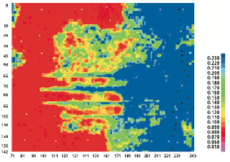
Figure 1, Relative water movement along faults in Ghawar (Dogru et al)
It is also evidenced by this simulated model of the effect of high fracture densities on the performance of MRC wells, where increasing the drawdown pressure to pull fluid into the wells can lead to premature watering out of the well.
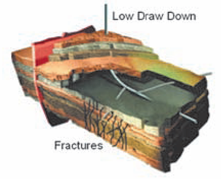
Figure 2. Use of a low drawdown pressure to maintain oil flow.
With low draw down, the flow rates are reduced, but the fluid entering the well remains largely oil (Mubarak et al)
In contrast, if the differential pressure is increased by lowering well pressure, then the greater flow rates allows the underlying water to flow up the fractures and prematurely waterflood the well.
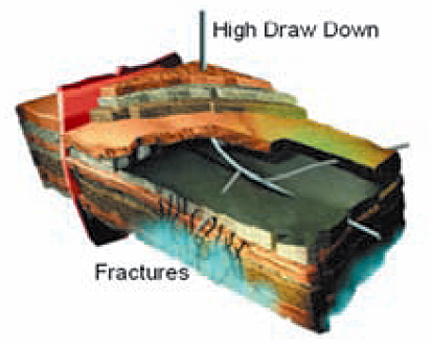
Figure 3. The use of a higher draw down pressure preferentially encourages water migration up the fractures, killing the well prematurely. (Mubarak et al)
It has been obvious to Aramco (who runs the KSA fields) for some time that adding their own fracture paths to the field would result in better performance, and could also help overcome the problem of natural fractures and high-permeability zones such as the Super-K in Ghawar.

Figure 4. Section through conventional dolomite at Ghawar (Cantrell et al)
Contrast this with the blue epoxy-filled pores of the super-K layers which indicate the high permeability.
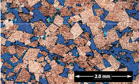
Figure 5. Section through the super-K dolomite (0nly 5-ft from the sample in figure 2, in the same well. (Cantrell et al)
There is thus an incentive to provide paths for the oil to make it easy to reach the well. What follows is a more advanced discussion of hydraulic fracturing, but for those who are not that interested, the earlier simpler description is given here (TOD and BTE).
Now, just a little bit of extra tech talk. If you take a rectangular piece of Plexiglas - which gets around the geological variations in properties that occur with rock - as an example - and carefully cut a notch into the center of the block, you can grow a crack out from that notch by putting the beam into simple 3-point bending. (We started doing this because we wanted some experimental results to compare with the various theories predominant at the time over the stresses required to initiate fractures).
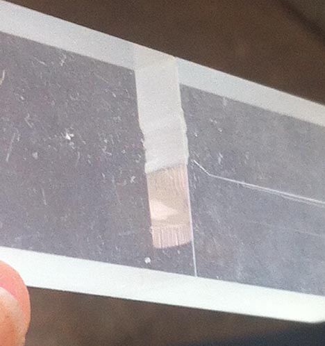
Figure 6. Crack grown out from a wire-sawn notch in Plexiglas, under 3-point bending.
One of the first practical steps you take is to stop using a wire saw for the entire crack, but cut most of the notch with a milling tool, and only use the wire saw for the last few mm. The reason is that the heat on the wire causes a high failure rate of the cutting wire, particularly with a set of neophyte graduate students, and the wire, being diamond impregnated, is very expensive.
The next thing that you learn is that if you adjust the crack length, you can grow the crack very slowly and stop ii where you want, so that it is fairly easy to work out how much force you are putting in relative to the crack surface generated, as well as the force required to start the crack. Further, the surface of the fractured surface has a characteristic look, which we called “river lines.”
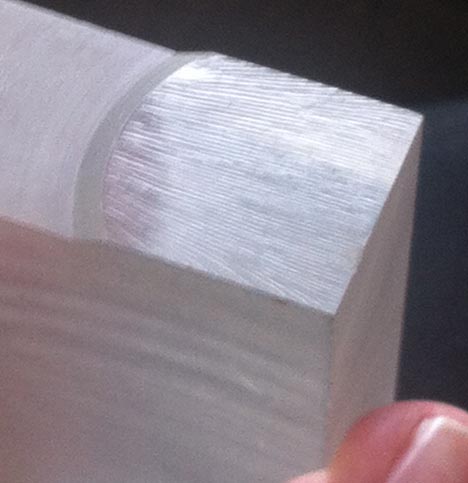
Figure 7. Surface of a crack grown out slowly from the initial notch (finger for scale)
However, if you changed the notch length so that so that it was less of a percentage of the sample width, the crack almost immediately moved much faster, and unless you made a special effort, could not be stopped within the sample (as occurred in Figure 4). And further, the crack surface was very smooth, in contrast with the "river lines" of the slower moving crack.

Figure 8. Crack grown from a shorter notch, with a higher speed of advance in the sample, note the smooth surface.
What this shows is something that Dick Bieniawski was also finding in rock itself (as we later also demonstrated). Depending on the initial length of the crack, so the speed that the crack grows at changes, and at the higher speed it moves not around the particles of rock, but often through them. (In our case we were seeing the effects of discontinuities in the Plexiglas as the cause of the deviations in the surface). Dick’s work is given here and here, though I found it in the International Journal of Rock Mechanics and Mining Science (vol 4 no. 4 pp 395 – 430).
Essentially he found, and this has been confirmed by others based on initial geometry,that a crack begins to grow relatively slowly, but then accelerates to a terminal velocity that remains relatively constant. Unfortunately, the papers are behind a paywall, so I cannot use the exact curve that Dick drew, but I am going to approximate it, as follows:
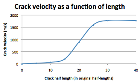
Figure 9. Change in crack velocity with length (after Bieniawski IJRMMS)
(Half lengths are used, since for many theories the crack is anticipated to initiate as an oval shape. For the fractures in the field these are usually measured in tens of feet. (Rahim and Al-Qatani)
There are two critical points that come out of this work. The first is that it is preferable to start with a crack of a significant length so that the acceleration rapidly moves to a trans-granular surface rather than just growing around the grains. The reason for this is practical in that small cracks can be stopped if they reach an area with a large radius (the reason you drill a hole at the end of a crack to stop it growing through a sheet of metal). Having the crack initially moving faster means that it can overcome small open spaces, and also that it can create a smoother, slicker path along which fluid can flow with less resistance.
The other aspect of growing the crack is that if you try putting too much energy into it (for example, by over-pressuring the borehole) the crack will not grow faster; rather it will expend the additional energy by splitting into a number of cracks that deviate off somewhat from the original direction. That also tends not to be a good thing if you are trying to open a single passage way through the rock, wide enough to push particles into, along with the fracturing fluid. To stop that from happening one can, for example, pulse the pressure in the well so that only enough energy gets to the crack tip so as to keep only a single fracture growing out. One also has to ensure that the crack is initiated within the right orientation to the existing stress fields. Aramco have, however, become skilled in determining the effectiveness of the fractures by monitoring, among other things, the temperature flows of fluids into the well.

Figure 10. Induced fracture and the evidence for it from the temperature log (Rahim and Al-Qatani )
Aramco have started to use hydraulic fractures in their horizontal wells, including those with open hole completions with the interval between packers ranging from 100 to 1000 ft, depending on geology.
The pressure within the packed off section of the horizontal well is then increased until the wall fractures and the crack grows out into the formation. An example of how the pressure changes in the well as the fracture grows is given by Al-Naimi et al.
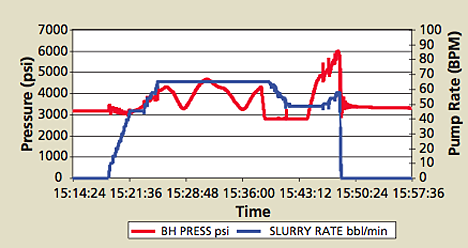
Figure 11. Pressure plot during the generation of a hydraulic fracture (Al-Naimi et al).
Getting the rest of the oil after the best is gone is an ongoing effort, particularly in older fields such as Ghawar. But understanding some of the technology makes it possible to further appreciate what Aramco is developing to further produce some of the more difficult regions within the field. That is a topic for another day.
Contact
- Content: editors at theoildrum dot com
- Tech support: support at theoildrum dot com
License

This work is licensed under a Creative Commons Attribution-Share Alike 3.0 United States License.
Thanks for the interesting details. Is there a marked difference in the elasticity of various type of rock, and does that make accurate pressure control more difficult? Also would it affect the amount of pump work involved?
In the example shown in Figs 2 & 3, it looks like you're working in a fairly narrow zone between water and cap rock. Is that pretty typical, and are there significant problems with fracturing the cap layer?
The parameters that we worked with were more related to toughness (which is a debatable property), and surface energy of the constituents of the rock. But once you have some information from initial testing, which includes (as the paper I linked to shows) the stress orientation and existing cracks then it becomes not too difficult to predict the pressures needed to start, and then keep the crack moving without getting too much energy to the crack tip. There is also a flow volume issue, since you are pumping fluid and particles into the crack as it opens, and the gap created has to be large enough to pass the particles and not filter them out. Thus the monitoring of both fluid pressure and flow rates during the fracture.
KSA are trying to use radioactive tracers to determine crack size, but my sense is that, so far, it has only a limited range. Fracturing the rock is a benefit in only some situations, and I may have confused the issue by showing the problem with natural fractures (Figs 2 and 3) where the pictures are illustrative of oil recovery at the end of a field's life, going after the attic oil, in contrast with some of the current fracture work, which may be further down the flanks of the reservoir, where the wells are going after stranded oil, or where fractures are being placed so as to help change the overall characteristic of the reservoir to counter high permeability zones.
There is generally enough experience in the fields that are being fractured (particularly when working with existing joints and fractures) that operators can control the fracture growth to ensure it remains within the reservoir, and does not threaten the integrity of the cap rock. Being of different materials, and with the cap rock being generally tougher (because of the smaller particle sizes - which are one of the properties that make it a cap) the amount of energy required to carry the fracture into the cap would be significantly higher than that in the reservoir.
HO
Is figure 11 telling us that frac'ing this zone took about 30 minutes? And thus,
if I'm fracing 24 zones in a long horizontal well, the process would be completed
in less than a day? I've read somewhere about ceramic "balls" being used to isolate
different sections of the horizontal well bore. Perhaps in a future post (or in a previous one?)
you could describe the mechanics of a multi-state frac job.
Steamflood at Wafra moving closer to breakthrough
It should be noted that rock will fracture generally along one axis in preference to two others. In sedimentary rock that typically is along the plane of the foliations. To preclude fast water flooding the well should be in relative flat laying portions of the rock in preference to steeply dipping protions.
Rich,
Not sure I can agree with that statement. Hydraulic fractures , both naturally and anthropogenically (Haliburton)induced, will be oriented perpendicular to the direction of least principal stress. In other words vertical, in most cases. Propagating horizontal fractures would mean 'lifting' the overburden, ~ 1 psi/ft depth. Horizontal fractures occur mainly at shallow depths and in areas of compressional stress (thrust faulting).
Observed fractures coincident with bedding planes in cores are often the result of the drilling and recovery process.
Not sure I agree with your last statement either, but I don't know what it means.
Frank.
I'm no expert... but what F Riggen says sounds exactly like what Hubbert and Willis found in their classic paper, "The Mechanics of Hydraulic Fracturing" (1957): j.mp/KHDKlS (link to pdf)
It says: "... the fractures produced should be approximately perpendicular to the axis of least stress." That is, the cracks open in the direction that requires the least amount of energy. Their demonstration showed that in most situations this would be vertical.
That little qualifier "approximately perpendicular" hides what can be complications with significant impact. If the initial crack is not oriented correctly (bearing in mind that historically it has been driven using small shaped charges, though there is now a move toward high-pressure fluid cutting or enhancing of the initial crack shape) then this changes both the initiating pressure, and also the path that the crack will take, so that while it may swing round to the right orientation it does this through a transition curve, which can muck up the flow stream a little over that desired, with a resulting negative impact on performance.
This answers my questions, as I was scratching in head a bit on how they managed
to start with a crack of a significant length so that the acceleration rapidly moves to a trans-granular surface rather than just growing around the grains
Controlling the starting part seems pretty tricky to me.
The pictures in figures 7 and 8 are a bit fuzzy. Are the small groves on the surface in figure 7 the slow growing cracks? I'm not certain what I'm looking at.
Many northerners have witnessed crack acceleration up close and personal. Apply the right bending (rough road twisting a windshield frame) or enough expansion differential (hot defroster air hitting the length of the bottom of an otherwise -40F windshield) and a small stone chip can generate a crack the races the length and/or width of the glass in an instant.
Natural Fracture Characterization from Microseismic Source Mechanisms: A Comparison with FMI Data
So how much of the ever-increasing price of oil is based on all the new investment needed to extract the hard to reach stuff? What's the cost to produce a marginal barrel in Saudi Arabia now?
In my opinion, the best metric is $/bopd and $/barrel reserves. From memory Dammam is at $12,000/bopd with (re)-development costs of $2.40/barrel. Manifa, I think is in the $17,000/bopd range and I don't recall development costs. Both are essentially easy oil by worldwide standards.
Berri field's development project from 2009-2010 may be relevant. HO's post of a few weeks ago covered that one, I'm not sure if costs were disclosed.
Enhancing Production at Berri
Chevron's Wafra EOR(steamflood) in the neutral zone is way more than either of those.
Frank