Turning an Oil Well and Down-Hole Motors
Posted by Heading Out on November 1, 2009 - 10:05am
This is part of the series of tech talk posts on how to get fossil fuels out of the ground that appear here most Sundays. In this post, I talk about several innovations in drilling, including down-hole motors. Among other things, down-hole motors made it possible to turn tighter corners with the drill bit, enabling horizontal wells.
The last post in this series dealt with directional drilling, where I had mentioned the need to go back in time to the period where the then Soviet Government was developing the Volga-Ural basin in the Soviet Union, back in the 1950's. And I quote from John Grace's "Russian Oil Supply."
In the Volga-Ural basin, however, particularly after recognition of the enormous potential of the deeper Devonian strata, drilling targets were further below the Earth's surface. Moreover, the older, more lithified rock of the Volga-Ural basin was harder. This required higher drilling torque, which in turn demanded superior strength drill-string steel. The Soviet steel industry was basically unable to provide high-strength drill string in volumes necessary to develop the basin.
Engineers responded with turbo-drilling, which does not depend on rotating the drill string. Instead, immediately above the bit, they placed a turbo drilling motor, which itself did the work of turning the bit. This obviated the necessity of twisting the pipe and thereby reduced the required quality of steel.
Turbo drilling radically increased the productivity, Combined with the growing number of rigs available, the total number of feet of development drilling conducted per year nationwide jumped from 1.9 million feet in 1949 to 7.1 million feet by 1950 and 12.1 million feet by 1960.
They were also developing waterflood techniques in the basin at the same time, and we have discussed that in previous posts.
The idea of putting a motor directly behind the drilling bit was not new, the first Russian turbine drill having been designed in the mid 19th century; however, it required a number of stages before the design could turn out enough power. And the first patent for an American downhole turbine was granted in 1873.
For those who are not familiar with a turbine drilling motor, essentially it consists of a set of fixed turning vanes at the top of the motor (the stator vanes) which direct the flow of mud going down the hole to flow onto a second set of vanes (the rotor vanes) which are pushed around by the flow, causing the drive shaft to which they are connected to rotate.
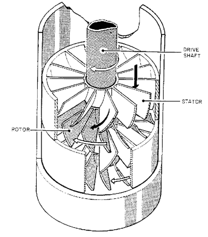
By combining a series of these stages together into a multi-stage turbine considerable torque, and speed, can be passed to the drilling bit which is attached to the rotating drive shaft.
Putting the motor at the bottom end of the drill string had a couple of other advantages. One is that it allows the hole to make angle, i.e. to turn in a tighter radius than if the whole pipe were rotating. While conventional rotary rigs can build angle at only 10 degrees per 100 ft, with a down hole motor the angle can build at 13-15 deg per 100 ft. The Russian idea took a while to catch on in the West and to his credit, a guy in Houston called Bill Maurer, had a fair bit to do with that. Time and technology have however moved on a bit since then, and Bill’s company was acquired by Noble Drilling Corp so I can’t pass on links to the firm.
With the advent of down-hole motors there is no need to have the complexity of joining 30-ft lengths of drill pipe together to deliver power to the end of the bit. This had always been constrained by the steel strength and joint limitations. Now that could be designed out, and the power could be delivered to the bit hydraulically through the mud, since this could be used to drive the motor.
Later motors have included positive displacement designs, such as the progressing cavity motors which Dyna-drill illustrates with an animated figure at their web site.
For those interested in relative performance, and the gains that technology can bring there is a case study available of a well drilled with a down-hole motor and PDC bits with a rate of penetration (ROP) of 93.5 ft/hr.
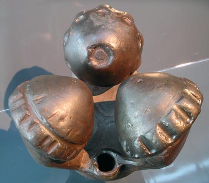
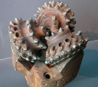
Turbine motors work best at higher speeds, but to create the chips and achieve effective drilling with conventional tri-cones, rotation speeds had historically been slow. And the problem remained of creating the high thrusts across the bit that were required for this type of drilling, when the motor turned faster.
One answer came in response to a second problem. As the rocks that have to be drilled became harder, so the forces used to cut through them also went up, causing a materials problem. The materials used to make the drill bits were either wearing out, or teeth were being broken out as the bits pushed through the rock.
Until now, we had tried to break the rock in compression by pushing the tooth into the rock. But if, instead, we dragged the bit across the rock without trying to chip it, in the same way as a metal-cutting bit on a lathe peels off a layer of metal, maybe we could lower the forces on the bit.
And if we used a diamond tool to do this, then while each diamond insert would only remove a very small amount of rock, we could impregnate a whole bit face with small diamonds (much cheaper than the single stone you buy for the intended, since they are much smaller, and more common). These diamonds can be dragged over the rock face and slice off very thin layers, but can do so when moved at a very fast speed. Putting the two together meant that a new drilling concept could be developed, and a new drilling bit.
The next development came about with the development of larger polycrystalline diamond compacts (PDC's or PCD's depending on your level of technical correctness). By making these larger diamond coated discs and setting them on the drill bit it was easier to circulate the mud so that it kept the diamonds cool.

This is important since, if you get the temperature of the inserts above about 3-400 degrees, the diamond starts to soften a bit and wears faster. In this regard the design of these bits is still not perfect, but it has become better.
The lower force required to drive these bits into the rock, and the ultimately faster ROP that they allowed meant that it became easier to consider turning the well, not only to some angle downwards to intersect an oil reservoir not directly below the rig, but that one could also turn the well so that it could be turned to the point that it was drilling a horizontal well.
And this had a lot of advantages – once the technique was developed. The first horizontal well that I know of was drilled at Rospo Mare in 1982, and it achieved a much higher initial and sustained production than vertical and slant wells in that reservoir. It was a technique also being developed for coal bed methane recovery, something still in development.
But I’ll leave that development, and more until next time.
The list of talks is getting longer, and as we are also getting a little more complicated, it might be more useful for those just finding this series go to the tech talk series, and read the posts in order, starting with my August 6, 2009 post (found on sheet 2). Because this is a relatively informal it is also prone to the occasional short cut, which may not leave things as clear as I would like. So please ask, if I need to give more detail, or if you know more feel free to comment.
Contact
- Content: editors at theoildrum dot com
- Tech support: support at theoildrum dot com
License

This work is licensed under a Creative Commons Attribution-Share Alike 3.0 United States License.
A question about a detail of Rospo Mare: the link points to an abstract of the technical paper in which I find
I sense that 'essentially conductive' is used here in a very special technical sense. This is somewhat comfirmed by the Google hits that I get when I search for "essentially conductive". But I can't really understand the meanings intended in the Google hits. So, I'm asking. What meaning does this phrase convey to a person familiar with petroleum technology? (In contrast, 'extremely different' doesn't appear to be anything more the harmless puffery about the importance of the authors' work.)
A karst formation is one where water migration through the rock has eroded channels and larger cavities, which can, relatively close to the surface fill up with mud, but which also give, through the passages that the water carved through the rock, an easier passage (hence conductive of fluid flow). The passages can be filled with different materials, and remember that the water erosion could have occurred at different times in the rock history so it is difficult to predict how they are oriented, and thus how to take greatest advantage of them. You might think of a series of interconnected caves to give a horizontal picture, or - as in the case in China - places where the landscape is dotted with tall towers of rock separated by deep gorges.
geek -- I'm notfamiliarwith this particuar formation but I'll offer some generalizationsabout such rocks. Karst generally refers to lmestone rocks which have undergone a good bit of dissolution. Every so often you'll see a story about a giant sink hole swallowing a car or or building in Florida. Often such a collapse is cause by the dissolution of the shallow limestone rocks by the slightly acidic ground water.
Such reservoirs are rather different then "conventional" sandstone and other types of carbonate reservoirs. But they can still be called conventional. No hard rule but conventional implies to me the hydrocarbons ar contained in the pores of the rock which have a good permeability (the measure of how well fluids flow through the rock = "essentially conductive"). Karst reservoirs can have very high permeability which can actually be a big negative when trying to drill. These rocks can be so conductive that the drilling mud (even if it's associated pressure isn't much higher of then the rock) will flow uncontrollably into the reservoir.
That sounds like an opportunity: just pump water rather than mud, and let the chips and such wash away into the porosity instead of trying to bring them back up the hole.
Thanks HO and Rockman and others for this great tutorial series.
Bio1
How did they know where the drill bit is? It is easy for me to imagine turning a drilling rig, but I find it hard to imagine how I know if it is turning in the desired direction, or just what angle the hole is heading. So there must be a whole other area of downhole technology that provides information about the whereabouts, and heading of the hole?
EOS - They get a telegram from the drill bit telling them where they are. Not kidding. The bottom hole drilling assembly has electronic sensors that determine the bit location. This information is sent to the surface via the mud column. The drilling assembly sends out a coded pulse similar to a telegraph dot/dash. Additionally, they'll occasional pump down in the mud a small metal tube with a similar electronic system which measures the hole's locations as it goes down. The tube returns to the surface and is downloaded. This allows a confirmation of the original direction survey. The system can be amazingly accurate. I once keep the drill bit in the top 3 feet of a reservoir that was over a mile and a half away laterally and 10,000' deep.
The mud pulse system was a huge advancement. If you've heard of "log while drilling" this is the system used to transmit that data to the surface. Instead of drilling the hole and then running logging tools down to see what's there, a variety of logging tools can be attached behind the drill bit and we can see what we're drilling through in real time. In fact, as I'm typing this message I have another window open and watching the LWD via a satellite link and can see the nature of the rocks we're drilling right now about 150 miles away here in Texas. Last year I sat in my home on weekends and received the LWD of a well in the Brazil Deep Water. I used that data to calculate the pressures in the rock and, in turn, transmitted the results to the driller on the rig so he could adjust his mud weights accordingly. Truly a whole different tech world then when I started 34 years ago.
Thanks! I like the image of the telegram, and may pinch it for use elsewhere.
You're welcome HO. I've always been tickled to by the thought of so much high tech depending upon dots and dashes. And then to have the signal transmitted through a fluid column thousands of feet long. It's easy to recall those early days when we had fits getting those signals through all the rig noise/vibrations. Gotta hand it to those development engineers.
This is fascinating!
So the drill must do what? hold onto the sides of the well and flex the bit in x,y,z.?
the drill pipe or drill control must be flexible?
I'm confused...
Is the mud( cutting fluid? right) pumped down a pipe, it has to be.
So I'm just confused..
has to be flexible pipe with mud under pressure, is the well cased or do you loose mud into cracks in the rocks on its return trip to the surface.
Filling cracks with mud wouldn't be good in the pay zone, 2 pipes one vacuum?
sorry a bit rambling
Grin:
This is part of a series of posts, so I am assuming that you have read the earlier ones first - in this case I talked about how and why we use the mud , and how it gets into the pipe and how and why the hole is cased in steel in earlier posts.
The pipe weighs 14 lb or more per foot, and while individual sections might be 30 ft long (or multiples thereof) the whole length down to the drilling bit is likely to be several thousand feet long, and thus has a considerable inertia. The mud flows down the middle of it, and given the wall thickness of the pipe. viewing it as flexible is a matter of opinion. One of the reasons for the mud is to fill small cracks in the rock, but as I noted in the post on completing the well you normally need to clean the walls of the hole in the reservoir, before can start production.
Incidentally, talking about earlier posts, I wrote about the Potter method for drilling rock, last August. I see that they just picked up $5 million for that work from DOE Geothermal last week.
Deleusional -- Some of the steering systems used seem to come out of scifi. There is a system that you program the course you want to follow into the downhole computer built into the drilling assmebly. The drilling assembly then monitors its position to see if it's following the course. If not there are cams in the drilling assemble which then push the drill pipe in the direction it needs to go to adjust the course. If it all works properly all the driller does is keep the proper weight on the bit and the pumps moving the mud through the DP at the correct speed. And the down hole steering system takes you where you want to go. And if you decide to change course from the original plan you can send a message to the down hole system via the telegraph like message system I described earlier and give it a new course.
Loosing drilling mud to the rocks is not an uncommon problem. It can be a fine balance between having a high enough mud weight to keep the well from blowing out and being too heavy and loosing mud to the rocks. It happens in the open hole and not the casing as a rule. But every now and then you can get a hole in the casing or, more likely, at the base of the casing where the cement holding the casing in place will fail and you loose the mud "at the shoe" = the bottom of the casing.
Thank you both. It is interesting.
I'm curious regarding this as well. A lot of the technology used in the oil industry simply blows me away.
Yes, as am I. I would think that the possibility that the drill pipe might have twisted by an unknown amount would mean you don't know which way your sensor log is pointing. Now given modern electronics, perhaps inertial systems are good enough now. But, they've been doing this for decades, so something pretty clever must have been worked out a long time ago.
I'm struggling with the idea of mud driving the drill bit, presumably because my concept of 'mud' - the stuff I dig through on a wet day in the garden - is incorrect in this context. How viscous is it? Is there a down tube and an up tube in the well, and how wide are these? Is the mud manufactured at the well head by adding water to something, or do you have tanks full of the stuff being delivered?
As HO mentions at the end of the post, this is part of an ongoing series. I look forward to the Sunday posts and knowledgeable comments near as much as I looked to the Sunday funnies as a kid--keep 'em coming HO, ROCK and everyone else.
here is the 1ink to the post on mud. The tech talk link gets you to all the posts of this series and its predecessor. One stop shopping :-)
I think the link is incorrect:
http://www.theoildrum.com/node/564 --> "Go ahead and drive less"
should be
http://www.theoildrum.com/node/5641 --> "Mud, mud, glorious mud*"
what a difference a "one" makes.
thanks I guess my sloppy mouse work made me more hindrance than help, I'll test run my links from now on.
buggie -- Though we use a rather simplistic term "mud" it's fairly complex chemistry. Simple parameters are mud weight and viscosity. MW is given in lbs per gallon. A normal weight is 9.0 ppg. When you drill higher pressure reservoirs the wt can reach 18 ppg. Viscosity can range from slightly thick water to rather stiff. Then there a whole additional world of PH, salinity and a variety of other qualitites. There's a physical side of the process...primarilly pump rate.
The mud goes down the inside of the drill pipe, goes through a down hole motorif that's how you're set up.Then the mud goes out nozzels in the drill bit and help lubricate/cool the process. The mud returns to the surface in th area between the bore hole and the drill pipe (annulus). Bach at the surface the mud goes through a screening process and the cuttings are removed. Then it's pumped back down the drill pipe again. The mud parameters are constantly monitored and adjusted as required. We call those guys mud engineers although "mud wizard" is an affectionate term used sometimes.
I'm not quite sure I understand how the turo-drill reduces the load on the drill string. If there is a certain torque applied to the drill face that torque has to be reacted against something. I can guess that friction in the string rubbing against the bore wall might react some of the torque, reducing the load on parts of the string farther up but it seems that the entire drill string must still need to supply a considerable amount of the reaction.
I've read that the flexibility of a drill string could be compared to the flexibility of a three foot long piece of cooked spaghetti. Seems like not having to turn an entire two or three mile long string would substantially reduce the total torque load the system had to bear.
jj -- When you're drilling with down hole motors you're not typically rotating the drill pipe. It's only moving vertically so the isn't mush of a torque factor involved. The key parameter related to the drill pipe is the "weight on bit"...WOB. Too much WOB and you'll induce too much torque at the bit and stall the mud motor. Too litle weight and you won't get a satisfactory penetration weight. Drill pipe torque was a big problem in the old days when you had to rotate the drill string. A cute oil patch term: twisting off. Refers to either excessive torque causing the drill pipe to break or getting drunk...especially the night before you start a 12 hour hitch.
This is a graph I found on an EIA Website showing the cost per foot drilled on a "real" ($2000 cost level) basis. Clearly there has been a big increase in sophistication of the equipment, contributing to the higher cost. Also, drilling is being done in less hospitable areas.
I notice from Baker Hughes data that the portion of drilling rigs that are "horizontal" starts growing about 2004. (It was fairly flat in the 1991 to 2003 period.) Percentage of horizontal drilling rigs, at the end of each year is as follows:
2003 9%
2004 10%
2005 15%
2006 20%
2007 25%
2008 34%
2009 (Oct 30) 46%
So there seems to have been a huge change in the last few years--perhaps contributing to the run-up in average cost per foot drilled.
Very interesting chart Gail. Could you tell if they really mean driling costs as opposed to total well costs including the completion? It's easy to guess why the ramp up the last few years: Deep Water GOM and the shale gas plays. A 34,000' DW well at $150 million is $4,400/ft. An expensive high pressure S. La well drilled to 17,000' at an $8 million cost = $470/ft. A SG well at 10,000' with a 5,000' lateral costs around $8,000,000. That's about $533/ft. To drill 15,000' of normal pressure vertical hole would run about $100/ft.
The DW wells would skew the average due to extreme costs and the SG would do likewise given the huge number drilled. If the chart doesn't represent the completion costs then the SG per foot cost would be lower but they would still make up a large portion of the population.
Thanks for the tech talk segment that you do on Sundays. They've really been entertaining for me the past two weeks. My father started directional drilling in 1958 for the old Eastman company and found himself working in the same company as his brother when Eastman bought out whipstock incorporated a couple years later. My father has been on some really big projects such as drilling the delienating wells on what would become the Ekofisk field in Norway back in the late 60's from the Gulftide jack up. Later he was the directional driller on Statfjord B also in the North Sea. I've only been directional drilling for 5 yrs now. However I have an uncle, and 3 first cousins who all followed in the family footsteps, and between the 6 of us we combine for over 100 yrs in the directional drilling profession. I'm currently laid off and honestly I'm loving every minute of it as the Barnett boom almost worked me to death for 6 years.
Your following two pieces are as concise as they should be for this discussion. However, I would like to point out another form of deflection besides the whipstock that you failed to mention last week that was also key in the development of multiple wells off of single platforms in the offshore fields. That would be "jetting" where the bit would be run on a "building assembly" and 1 of the 3 jets would be left out to constitute high side of the BHA. This was key so that the wells could be nudged away from each other directly below the drive pipe.
To give some history behind EOS's comment on the measurement or survey and logging while drilling to telegrapgh info to the surface is correct. I began LWD in the GOM as soon as I got out of school. However this technology was at first unreliable and didn't truly catch on until the mid to late 70's. The earliest survey techniques that were employed were primitive indeed and were known as single shots. Where an instrument barrel would be lowered into the hole. Within this insturment barrel, a small camera was situated directly above a film negative with a plumb bob hanging over it. After timing the decent to bottom, the camera would take the picture, the barrel would be spooled back up to the surface and the negative which was a round disk would be put into a container to be developed. The disk was ringed in varying circles from inside to outside. The closer that the shadow of the plumb bob was to the center, the straighter the hole was. And by knowing how many degrees were represented by each ring, the DD could report how many degrees of angle were in the hole. This very simple method was later upgraded to include a compass and a non magnetic drill collar so that the DD could actually put a direction and angle on the survey and enable him to plot an inclination and direction to follow a well plan and hit a geologic target.
One last comment for Heading out. The statement made that you make about the lower force (I'm assuming you mean WOB) to turn a PDC bit is true only in the fact that it does drill faster with less weight. However you continue on and imply that this also helps to drill a horizontal well. If you're talking about its role in the lateral of a shale like the Barnett. Then sure it is important. But when you're building a curve with a steerable assembly such as a 2.38 deg housing then the PDC bit was found out early on that it was not an ideal bit for building angle because most of them produce to much cutting on the low side of the hole. "gauge" cutters located on the sides of most of these bits. These "gauge protection" cutters were great for the sake of drilling a gauge hole. However, when that PDC is on bottom drilling these same the side cutters only served to undercut the low side of the hole and cripple the BUR needed to land in the window. Espiecially if the mud has not been properly and weighted up. It wasnt always the case because lithologies of the formations in the Build section varied thoughout the Fort Worth Basn. And sometimes faults were present. However, more times than not and the hole showed signs of washing out. Every one the I've worked with in almost any area of the country would make a bit/curve motor trip and drill the curve with an insert bit. This allows you to increase WOB and create a better "push off" of the low side of the hole, causing the BUR to increase. Those were our experiences with that method.
One more thing readers should know is the every connection in the drill string is "supposed" to be torqued to spec.The MWD tool is torqued and high sided for the DD to adjust and scribe to the bend in the mud motor. After everything is torqued to spec and lined up, it is run to bottom with brief stops to fill up pipe and test MWD tool. Another question I think I saw earlier pertained to the accuracy of steering a 13k-14k foot string of pipe that is as someone told him, "like a 3 foot wet noodle". Most of the torque while sliding (course change) is confined to the first 60-90 ft behind the bit. Only when the Mud motor stalls will you see any of this torque transfer from the bit to the string and subsequently to the rigfloor. 1) the stiffness of the bottom hole assembly prevents most of the torque from traveling back up the hole and you're right, much of it ends up on the wall, espiecailly when rotating. However, when "sliding" or making a correction run and we have to keep the pipe from rotating and steer the well. You can easily see the torque downhole as displayed by the MWD display. The bit turns to the right just like a handheld powerdrill. And when it really starts digging, it produces reactive torque to the left just as would happen to your hand if you stalled the handheld. Mud is the most important component both from a safety standpoint and a hole cleaning and torque issues.
Thanks for this input - it is hard sometimes to decide what to include in the main post, and these additions really help to give folk a better idea of what is going on.
Geo -- Great add on. I hope the folks get a sense of the tech changes your kin have seen over the years. When I started 34 years ago drilling a well to 60 degrees from vertical was cutting edge. And you hoped you ended up somewhere in a 2000' diameter target. Now going 90+ degrees is taken for granted. And accuracy? A couple of years ago while drilling a horizontal well off the coast of Africa, my young (and female) DD (directional driller) told me and the drilling super she was a little concerned about our well path...we were getting a little too far off the well plan for her comfort. The DD informed us we were 19' low and 30' to the right of the plan. And this was when the drill bit was 12,000' down and 9,000' laterally. We told DD to make what corrections she felt was needed. After she left the super and I just chuckled. Yes...we old farts still chuckle. We weren't going to chill her enthusiasm for accuracy even though we could have been 500' feet off track and would have still drilled the well we wanted. But she was young and broke out at a time when such accuracy was common. Unlike Geo. Though a geologist I've shifted more to rig operations in the last 15 years. Ops is just more interesting and then there's the immediate feedback from getting it done right now as opposed to waiting a couple of years to see if your prospect works. For me standing on the drill floor next to a DD like Geo is a good day. Even if it's cold and rainy and I'm drinking coffee out of a tomato soup can. A good day indeed. Sitting here in the office in front of my monitor in the office only reminds me how much I miss the rig work. But in a few weeks I'll be back on the rig floor (on crutches, unfortunately) with my DD trying to hit another target in S. La. Can't wait.
Enjoy your days off Geo...no doubt you earned it. And it sounds like you saved a few of those paychecks. Good for you.
Thanks, as a hands on guy I really appreciate your view from the rig floor. Although I found a handy drilling term glossary I wasn't able to fathom the BUR acronym you used. Could you expand a some?
BUR is a term that we use on reports and paper work it stands for Build up Rate. BUR when building a curve to get lateral is the planned angle in degrees per 100' drilled to land the curve in the target window. In our case it was usually a 10' by 10' square at about 7800' TVD or true vertical depth. It is like our "glide path" to land the plane on the runway if you will.
Interesting this downhole motor drilling, tri-cone bits run normally at low rpm values. These motors have a much higher speed. How long is the bit life to day on such motors and at what wob values in for instance 17 1/2" holes?
Interesting this downhole motor drilling All Cars, tri-cone bits run normally at low rpm values. These motors have a much higher speed. How long is the bit life to day on such motors and at what wob values in for instance 17 1/2" holes?
That is riduculass...
Panaramama, have you never heard of the development of the Qatar offshore gas reservoir with 17 1/2 " turbine drilling?
hans .. are you referring to the Al Shaheen (sp?) Fld being developed by Maersk?
I think so. In the early days the Qatar Petroleum Producing Authority specified an urgent requirement for a 17 1/2" turbine bit that could drill 40 ft/hour for 25 hours; paper OTC 3735 presented at the 1980 Offshore Conference.
Bearing life is the problem and I am curious if the so-called motorbits of today meet this requirement?
Al Shaheen was an interesting project. I was up for one of the contracts for a geosteering geologist but had other commitments. The first phase was to drill 600 horizontal wells from 6 jackup rigs. Two geosteering geologists per rig. Would have worked a 28 day rotation. Really hated to miss the contract...would have kept me busy for a long time. Drilling 26,000' laterals would certainly put a big demand on all the equipment.
Rockman, in the eighties as technical service engineer we have been testing tri cone drill bits on turbine and down hole motors offshore Qatar and in the North sea. On the navidrill with good results and the turbine we had a dramatic bit failure by losing all three cones in the hole due to fatigue failure of the welds of a new bit design.
Maybe I have missed it but I haven't seen any mention of problems in pulling pipe once it has gone on a curved path. Is this a problem or does the mud flow lubricate the pipe string and keep wall friction to a minimum. It must be necessary to occasionally change drill bits during these operations.
Bio, to answer your question about the problems with pipe in horizontal drilling which is the most extreme scenario for torsion and compression on pipe, there are several things to consider. For example, while drilling horizontal wells in the Barnett shale or anywhere else I've drilled them. It is usually common practice to use the non magnetic drill collars which have a larger OD and smaller ID and therefore are not capable of bending or stretching like drill pipe which has higher torsional and compressional capabilities before fatigue and ultimate failure ie twisting off are kept out of the curve. In order to put transfer a sufficient amount of weight to the bit in a horizontal hole that may be 8000' in lateral and only 8000' true vertical depth, the DD calculates the target TD or final bottom hole location and runs enough drill pipe between his bottom hole assembly where the survey and logging sensors are located to finish the well with a string of say 12 drill collars placed in the string to finish without them ever having to go through the curve. This way you are able to provide enough weight to the bit with the weight of the drill collars in order to "push" the bit to total depth. The drill pipe that is between this "push pipe" as it is call even though it is more flexible and resistant to failure "twist off" is put through enormous strain and it is common practice for the operator to rent this pipe from a third party b/c the drilling contractor doesn't want their pipe to be put through this. Pipe isn't cheap. Espiecially during an oil/gas boom. The drill pipe and even the collars are inspected by a third party and weak joints are sent in as junk iron. hope this help. BTW with respect to your question about the mud lubricating or helping things in this respect to the pipe, no it doesn't really help the pipe. It does help the DD because the slicker the hole, the faster and more accurate the correction run or "slide" in the lateral. Often diesel is added to the mud to "slick" the hole and help the assembly slide without rotating. I've also been on jobs where a bead recovery system is set up and glass beads that look almost like sand are are added to the mud to make the string pull and slide through the lateral easier. Hope this helps
GeoDD: Your replies aren't threading correctly. When replying to a comment, click the "Reply" link on the comment itself rather than the "Post a comment" link at the end of the post.